POWER FACTOR CORRECTION OF MV/LV TRANSFORMERS
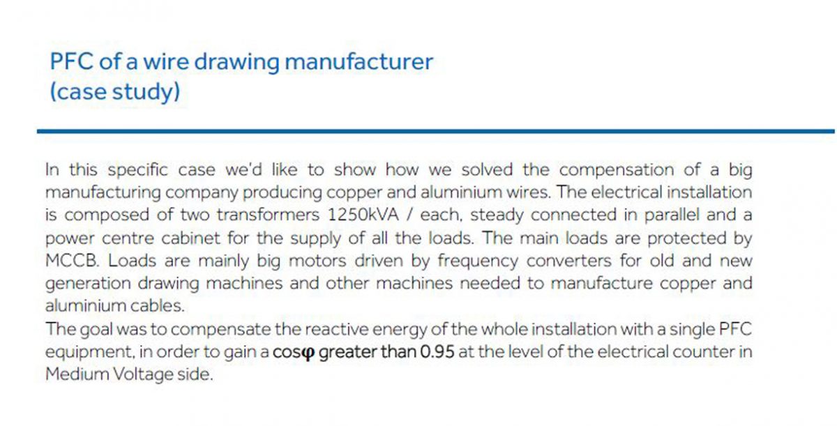
The transformers for the distribution of electrical energy can be made in two different types: oil transformers, whose cooling does not require special aids and transformers insulated in resin, forced or natural cooled.
It is always advisable to provide for a fixed power factor correction of the MV / LV transformers, since even if they operate without load (for example during the night), they absorb reactive power that must be compensated.
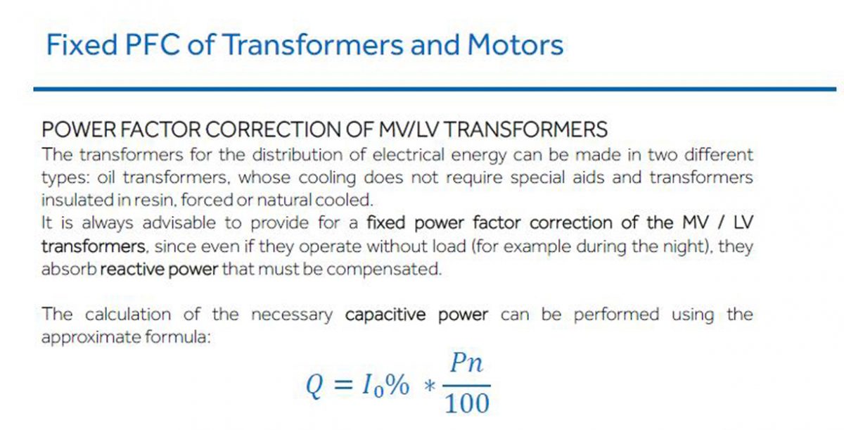
The calculation of the necessary capacitive power can be performed using the
approximate formula:

Pn = rated power of the transformer
Alternatively, if the requested data is not available, the following table can be used, differentiated by type oftransformerwith normal leakage characteristics.
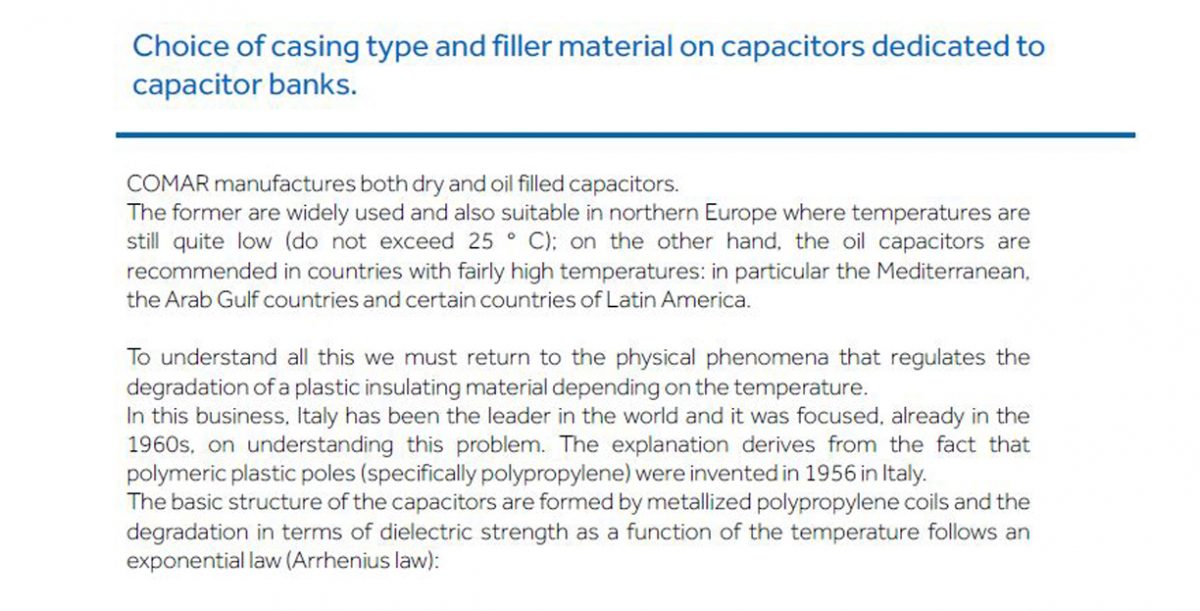
Approximately it is possible to tell that every 7 degrees of temperature increase means halfthe duration.
REACTIVE POWER REQUIRED for the VACUUM REFUSAL of MT / BT TRANSFORMERS (kvar)
(indicative values)
| Transformer power (kVA) | Transformers in OIL | Transformers in RESIN |
|---|---|---|
| 100 | 5 | 2,5 |
| 160 | 7,5 | 5 |
| 200 | 7,5 | 5 |
| 250 | 7,5 | 7,5 |
| 315 | 10 | 7,5 |
| 400 | 10 | 7,5 |
| 500 | 12,5 | 7,5 |
| 630 | 15 | 10 |
| 800 | 17,5 | 10 |
| 1000 | 22,5 | 12,5 |
| 1250 | 25 | 15 |
| 1600 | 30 | 20 |
| 2000 | 35 | 22,5 |
| 2500 | 45 | 30 |
| 3150 | 55 | 45 |
P.F.C. OF THREE-PHASE ASYNCHRONOUS MOTORS
One of the most common loads is the three-phase asynchronous motor, which can be rephased locally, with the advantage of having the power cable run through by a lower current.
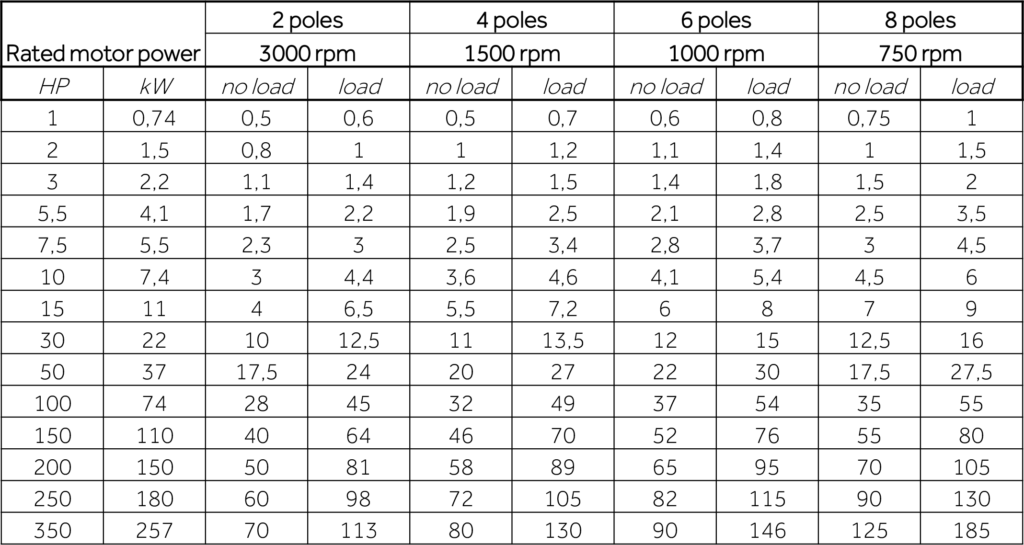
The capacitance of the capacitors must not exceed the reactive power at no load of the motor due to the risk of self-excitation and resonance phenomena between the capacitor and the inductance of the machine. The following table shows the power factor correction power in the case of a cage motor. For motors with wound rotor, an increase of 5% is recommended.
