In this specific case we’d like to show how we solved the compensation of a big
manufacturing company producing copper and aluminium wires. The electrical installation is composed of two transformers 1250kVA / each, steady connected in parallel and a power centre cabinet for the supply of all the loads. The main loads are protected by MCCB. Loads are mainly big motors driven by frequency converters for old and new generation drawing machines and other machines needed to manufacture copper and aluminium cables.
The goal was to compensate the reactive energy ofthe whole installation with a single PFC equipment, in orderto gain a cosφ greater than 0.95 at the level of the electrical counter in Medium Voltage side.
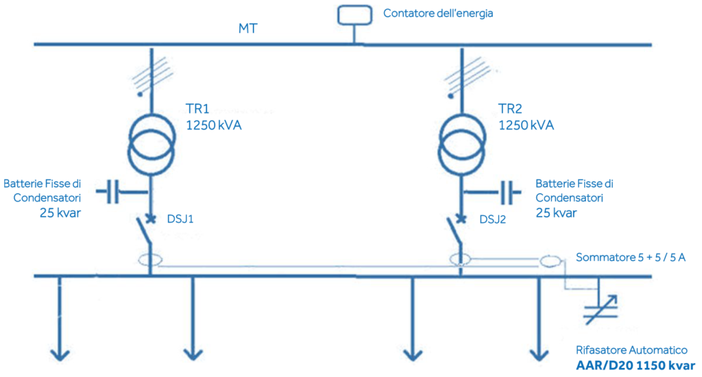
To meet this ambitious objective, above all, it was necessary to compensate the two transformers without loads. In order to be sure that all loads are well compensated (considering that it is almost impossible that the power from the two transformers is equilibrated), we have installed two CTs, one downstream of each main MCCB and a summationCT of 5 + 5 / 5A.
Here belowthe electrical scheme ofthe installation:
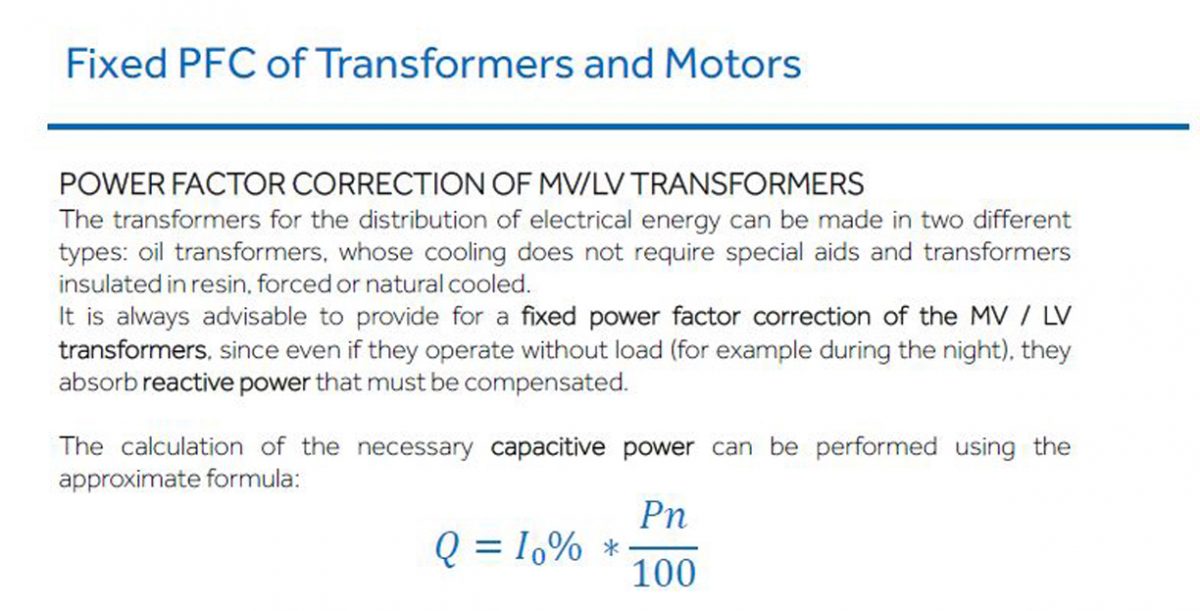
The two 1250 KVA transformers have a 2% no-load magnetic current, consequently we chose to compensate the no-load reactive power with 25kVAr fixed capacitors bank.
Below, the main results of the measurement campaign performed before PFC
installation:
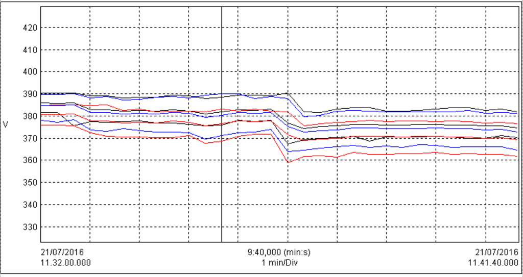
Voltage between Phases
| Name | Date | Time | AVG | MIN | MAX | Unit | Duration | Unit |
|---|---|---|---|---|---|---|---|---|
| U12 rms | 21/07/16 | 11.32.00.000 | 379,429 | 367,400 | 390,400 | V | 10:00,000 | (min : sec) |
| U23 rms | 21/07/16 | 11.32.00.000 | 374,124 | 358,800 | 385,100 | V | 10:00,000 | (min : sec) |
| U31 rms | 21/07/16 | 11.32.00.000 | 377,938 | 363,900 | 390,200 | V | 10:00,000 | (min : sec) |
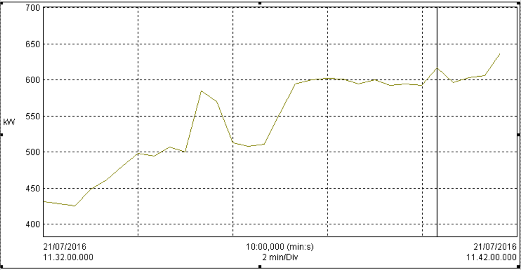
As you can see, when the production machines are activated, the voltage drops, due to a strong current demand. This fact is even more evident if we simultaneously analyze the graph below, ofthe variation in the total powerrequired.
Change in totalActive Power
| Name | Date | Time | AVG | MIN | MAX | Unit | Duration | Unit |
|---|---|---|---|---|---|---|---|---|
| PT (W) | 21/07/16 | 11.32.00.000 | 544,976 | 425,528 | 637,237 | kW | 10:00,000 | (min : sec) |
THD% in voltage and current
| Name | Date | Time | AVG | MIN | MAX | Unit | Duration | Unit |
|---|---|---|---|---|---|---|---|---|
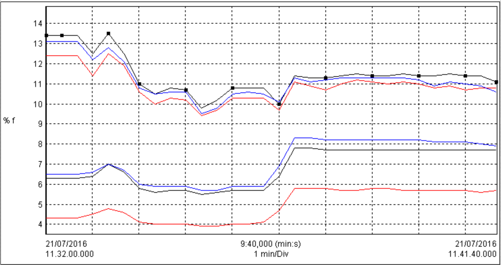
| A1 THDf | 21/07/16 | 11.32.00.000 | 11,450 | 9,800 | 13,500 | % f | 10:00,000 | (min : sec) |
| A2 THDf | 21/07/16 | 11.32.00.000 | 10,897 | 9,400 | 12,500 | % f | 10:00,000 | (min : sec) |
| A3 THDf | 21/07/16 | 11.32.00.000 | 11,190 | 9,500 | 13,100 | % f | 10:00,000 | (min : sec) |
| V1 THDf | 21/07/16 | 11.32.00.000 | 6,810 | 5,500 | 7,800 | % f | 10:00,000 | (min : sec) |
| V2 THDf | 21/07/16 | 11.32.00.000 | 4,923 | 3,900 | 5,800 | % f | 10:00,000 | (min : sec) |
| V3 THDf | 21/07/16 | 11.32.00.000 | 7,123 | 5,700 | 8,300 | % f | 10:00,000 | (min : sec) |
Change inTg φ
| Name | Date | Time | AVG | MIN | MAX | Unit | Duration | Unit |
|---|---|---|---|---|---|---|---|---|
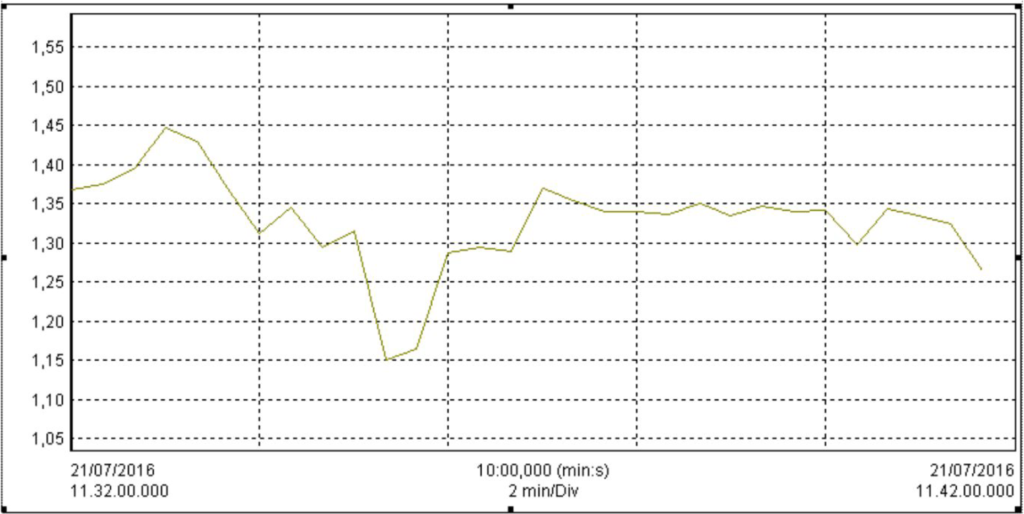
| Tan φT | 21/07/16 | 11.32.00.000 | 1,329 | 1,150 | 1,448 | 10:00,000 | (min : sec) |
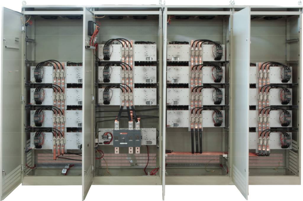
Considering this achieved data and a future extension of the plant for a new production line we recommended the installation of an automatic capacitor bank with Reinforced block reactors, type AAR / D20 (capable of supporting an Harmonic Distortion in Voltage THDVmax = 20%)with a power of 1150 kvar.
This capacitor bank is composed of the following steps: 2×25 + 50 + 4×75 + 5×150 kVAr, managed by the new generation regulator HPR12,with twelve output relays. The controllerwas setto reach a cosφ of 0.98 (Tgφ = 0.2).
To reach the aim of compensating at this high cosφ, the cabinet was designed with two steps of 25kVAr(the 2% ofthe total power).
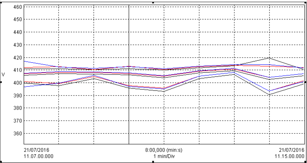
In this way we obtained a very good results in compliance with the customer’s requested specification. Furthermore the transformers are no longer overloaded, and they supply only the active current (the reactive current is residual) and the testimony of this fact is that the average voltage stabilized around 407V.
The series AAR / D20 capacitor banks is designed for particularly polluted networks such as cables manufactures, foundries, metal working like cold rolling, swaging, extrusion, coil bar and tube drawing.
Voltage between Phases
| Name | Date | Time | AVG | MIN | MAX | Unit | Duration | Unit |
|---|---|---|---|---|---|---|---|---|
| U12 rms | 21/07/16 | 11.07.00.000 | 406,171 | 390,500 | 419,600 | V | 9:00,000 | (min : sec) |
| U12 rms | 21/07/16 | 11.07.00.000 | 407,437 | 393,600 | 413,800 | V | 9:00,000 | (min : sec) |
| U12 rms | 21/07/16 | 11.07.00.000 | 407,827 | 393,400 | 416,800 | V | 9:00,000 | (min : sec) |
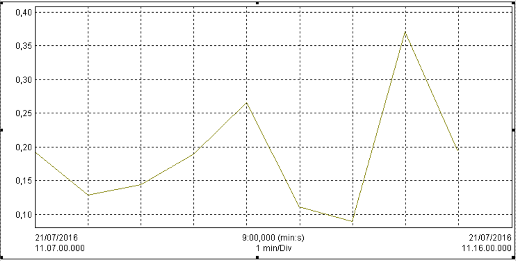
Below the graph of the Tgφ showing as the AAR/D20 PFC reacts to the variation of the power ofthe load.
Change inTg φ
| Name | Date | Time | AVG | MIN | MAX | Unit | Duration | Unit |
|---|---|---|---|---|---|---|---|---|
| Tan φT | 21/07/16 | 11.07.00.000 | 0,187 | 0,089 | 0,371 | 9:00,000 | (min : sec) |
